Statistical results for 2019
Find out moreOpen positions
Find out moreANALOG POWER FACTOR METER
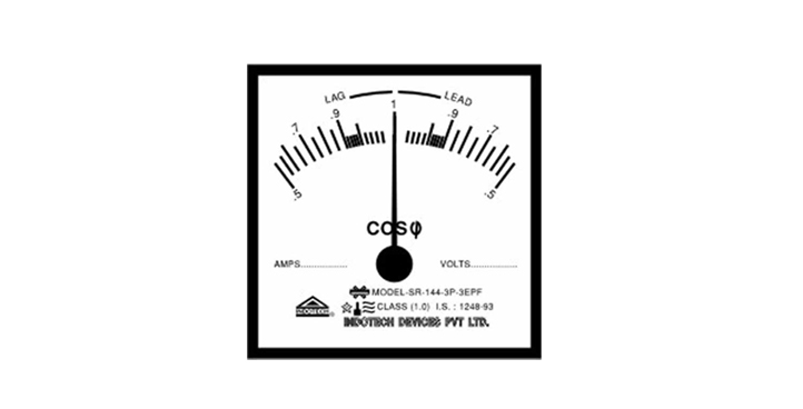
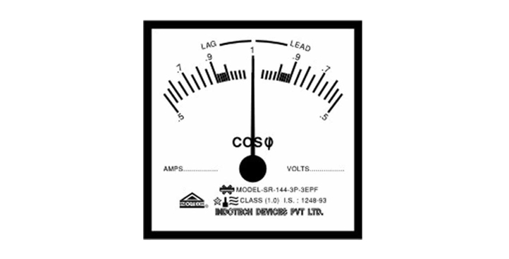
Indotech Analog Power Factor Meter – Indotech Analog Power Factor Meter measures the power factor of a transmission system. The power factor is the cosine of the angle between the voltage and current. Analog power factor meter determines the types of load using on the line, and it also calculates the losses occur on it. Indotech Analog Power factor meter, Analog Power factor meter, Power factor meter
The power factor of the transmission line is measured by dividing the product of voltage and current with the power. And the value of voltage current and power is easily determined by the voltmeter, ammeter and watt meter respectively. This method gives high accuracy, but it takes time. Indotech Analog Power factor meter, Analog Power factor meter, Power factor meter
Analog Power Factor Meter are designed to monitor changing power factor conditions on ir-reversible balanced and unbalanced load systems. The Power Factor is indirectly determined by measuring the phase angle Ø between current and voltage (both sinusoidal). However the movements are calibrated in values of cos Ø of the angle Ø. Scale is highly non-linear.
Purpose and Definition:
- The analog power factor meter assesses the cosine of the angle between the voltage and current in an alternating current (AC) system.
- It provides insights into how efficiently electrical power is being converted into useful work.
- Unlike digital meters, which display numerical values, analog meters use a moving pointer on a scale to indicate the power factor.
TYPE OF METERS : POWER FACTOR METER
Types of Analog Power Factor Meters:
- Electrodynamometer Power Factor Meter:
- Consists of fixed coils (acting as current coils) and a moving iron system.
- Has two identical pressure coils (A and B) pivoted on a spindle.
- Coil A has no inductive resistance, while coil B has a highly inductive coil.
- The current in coil A is in phase with the circuit, while the current in coil B lags by approximately 90 degrees.
- The meter’s moving coil is connected through silver or gold ligaments to minimize controlling torque.
- The pointer remains in equilibrium when the torques acting on coils A and B are equal.
- Used for testing the power factor of balanced loads.
- Moving Iron Type Meter:
- Includes a rotating iron and a moving iron cylinder.
- Measures the phase angle (cosine of the angle) between current and voltage (both sinusoidal).
- Calibrated in values of cos(Ø) of the angle Ø.
- Additional Information:
- Analog power factor meters are available in different sizes, such as 72x72mm and 96x96mm.
- They typically operate at voltages of 415V and 440V.
- Accuracy class: Class 1.5
SPECIFICATION : POWER FACTOR METER
| Test | Result |
| ACCURACY | Class 1.0 as per ISS 1248/03. |
| SCALE | Almost linear from 1/10 to full scale in case of WATT/KW/MW, VA/KVA/MVA & VAR/KVAR/MVAR Meters & 0.5 (Lag)-1-0.5(Lead) in case of power factor meters. |
| TYPE : | (a). Single element type for single phase A.C. measurements. (b) Single element type for 3 phase balanced load. (c) 2 elements type for 3 phase 3 wire balanced & unbalanced loads. (d) 3 elements type for 3 phase, 4 wire balanced & unbalanced loads. |
| RANGE | Current 1A or 5A & voltage upto 600V with internal resistance. Higher ranges with CT’s & PT’s. |


